


|
| |
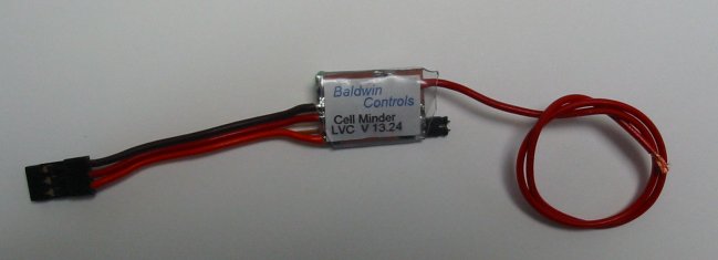
LVC Instructions
The Baldwin Controls Cell Minder LVC is designed to prevent over discharge of batteries on electric airplanes by shutting down the motor before the batteries reach a level that could damage them. It can be used with up to 5 Lithium Polymer cells, or with up to 16 NiCd or NiMh cells. It can be set up to automatically set the cut off voltage based on the number of LiPoly cells or the voltage of NiCd or NiMh cells, or set to a fixed cut off voltage. The Cell Minder LVC will correctly recognized the number of LiPoly cells even if the pack is partially discharged, however if a pack is hooked up that is totally discharged it could be recognized as a lower cell count, and the cut off voltage set too low. The Cell Minder LVC will have to be set up before it can be used. It has to be programmed for your idle setting and full throttle, cut off voltage, and type of cut off. It will work with standard direction speed controllers (2 MS pulse width for full throttle), as well as reverse direction speed controllers (1 ms pulse for full throttle). Throttle direction will be automatically set during set up. If the CellMinder LVC is set to autodetect Lipoly cells, it will flash the LED to indicate the number of cells found (3 flashes for 3 cells, etc) when it is first powered up, afterwhich the LED will light when battery voltage is above the programmed cut off voltage, and go out when the voltage is below the programmed cut off voltage.
SET UP
- The battery voltage sense wire will have to be attached to the positive battery wire on the electronic speed controller (ESC). A short battery extension can be made up with two connectors, one for the battery and one for the ESC with the battery voltage sense wire soldered to the positive lead to make it easy to remove the Cell Minder LVC, or the battery voltage sense wire can be attached directly to the positive battery wire on the ESC to keep it as light as possible.
- Make sure that the transmitter is set up to operate correctly with the ESC before the throttle controller hooked up.
- Make sure the battery is disconnected from the ESC.
- Unplug the speed controller wire from the throttle servo connection on the receiver and plug it into the Cell Minder LVC. Make sure this plug is plugged in the proper direction as per the wiring diagram.
- Plug the lead from the Cell Minder LVC into the receiver where the ESC was plugged in.
- Remove the jumper on the throttle controller to put it into set up mode.
- Turn on the transmitter, place the throttle stick at idle.
- Connect the battery to the speed controller and turn on the switch (if it has one).
- After a few seconds the LED on the Cell Minder LVC will begin to flash. At this point there is no rush. The Cell Minder LVC can stay in this state indefinitely.
- Move the stick all the way to full throttle (the motor will not run). After a few seconds the LED will begin to flash slowly. Count the flashes, and return the stick to idle as soon as the appropriate selection is reached as shown below;
| 1) Auto detect lipoly 2.8 volts per cell | 17) 11.0 volts |
| 2) Auto detect lipoly 3.0 volts per cell | 18) 11.5 volts |
| 3) Auto detect lipoly 3.2 volts per cell | 18) 12.0 volts |
| 4) Auto detect NiCd/NiMh | 20) 12.5 volts |
| 5) 5.0 volts | 21) 13.0 volts |
| 6) 5.5 volts | 22) 13.5 volts |
| 7) 6.0 volts | 23) 14.0 volts |
| 8) 6.5 volts | 24) 14.5 volts |
| 9) 7.0 volts | 25) 15.0 volts |
| 10) 7.5 volts | 26) 15.5 volts |
| 11) 8.0 volts | 27) 16.0 volts |
| 12) 8.5 volts | 28) 16.5 volts |
| 13) 9.0 volts | 29) 17.0 volts |
| 14) 9.5 volts | 30) 17.5 volts |
| 15) 10.0 volts | 31) 18.0 volts |
| 16) 10.5 volts | 32) 18.5 volts |
- Advance the throttle to full throttle again. Again there will be a delay, and the LED will begin to flash slowly. The number of flashes before returning the throttle to idle will set the type of cut off that will be used
- 1 flash-hard cut off: any time the battery voltage goes below the cut off voltage for more than one second, motor power will be cut to idle. If the transmitter is brought down to idle, then back up, the motor will again run until low voltage is seen for one second.
- 2 flashes-soft cut off: Once voltage goes below the programmed cutoff voltage, maximum throttle will be slowly reduced or increased to a level where battery voltage stays close to the cutoff voltage.
- 3 flashes-pulse mode: the throttle will be rapidly lowered when battery voltage is below cut off voltage, and raised when battery voltage is above cut off voltage, causing the motor to surge, making it easy to recognize that cutoff has been reached.
- 4 flashes-stutter mode: the throttle will immediately be set at idle when battery voltage is lower than cut off voltage, and throttle will immediately be set to the current stick position if battery voltage is above the cut off voltage. Stutter mode is not suggested for speed controllers that have a brake that immediately sets when stick is set to idle.
- Turn off the power switch on the ESC, or disconnect the battery. Replace the jumper to put the LVC back into run mode. The LVC is now ready for use. This set up procedure only needs to be run once, NOT every time you fly, but the setup procedure can be run again at any time to change the settings.
|
|